| <==Back | Next==> |
| Oct 14, 2006 | |
|
|
|
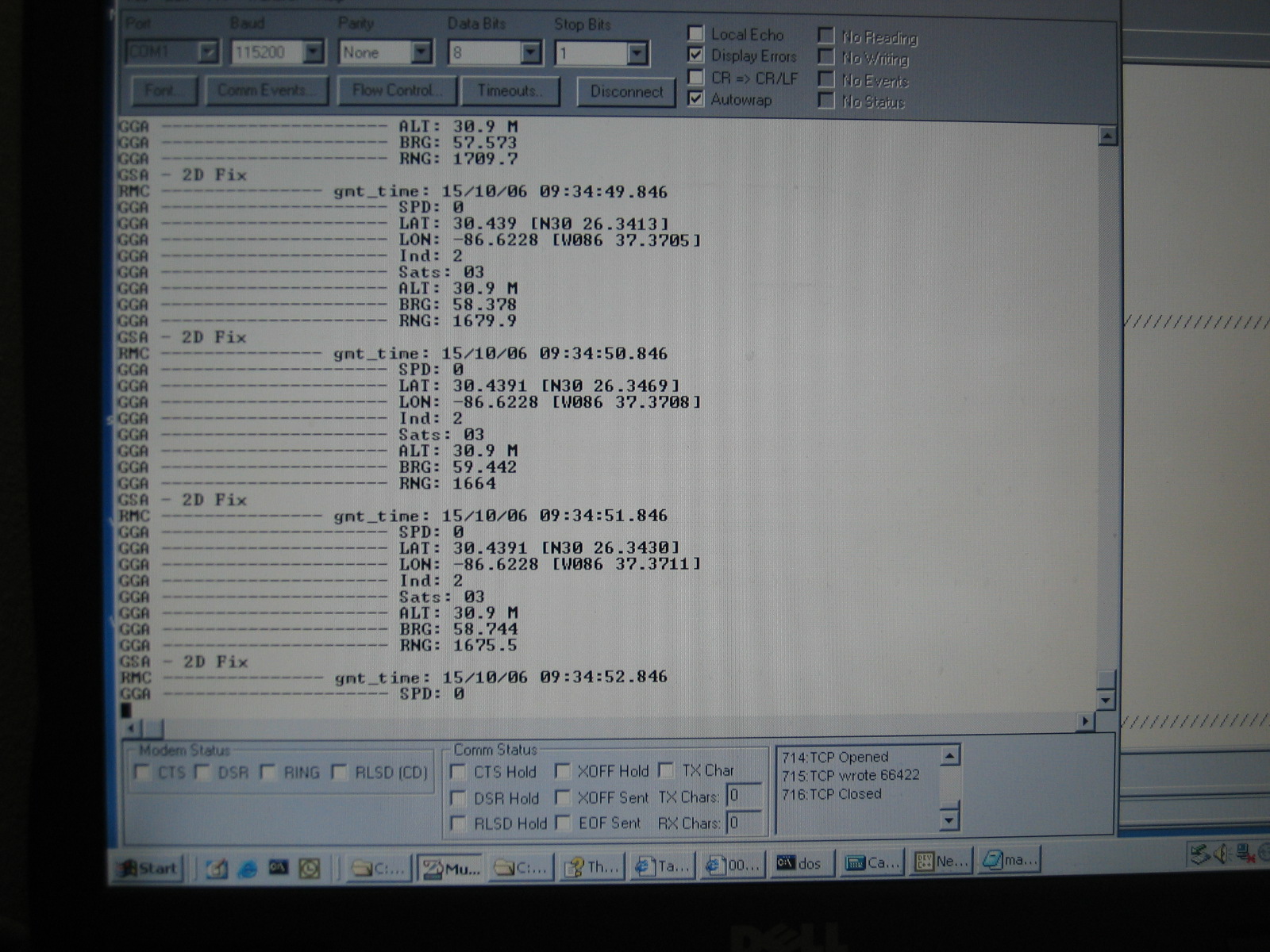
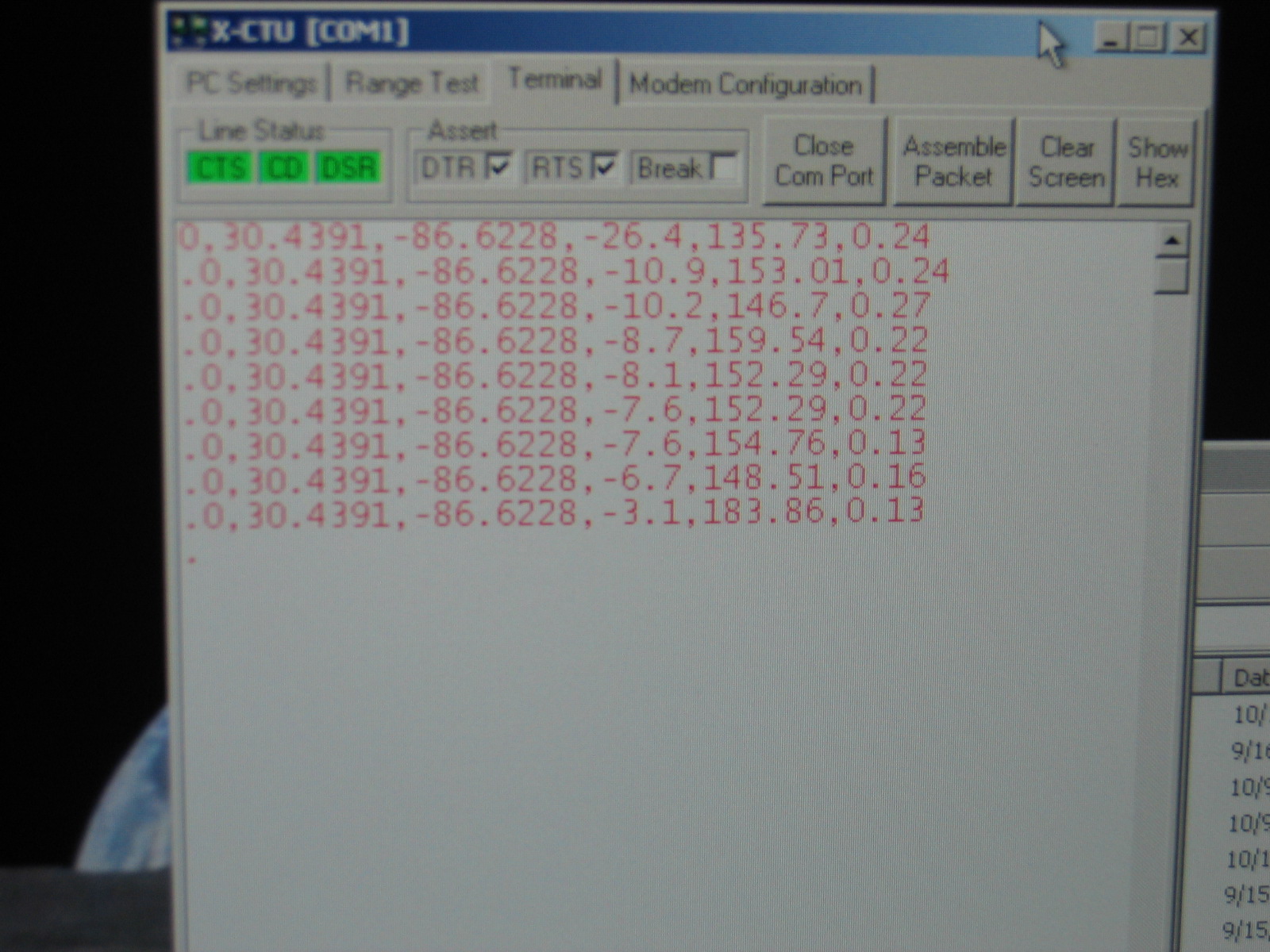
| Here's more NMEA data from the GPS module. The difference here is that the data shown is actually the parsed, converted values (mostly float values) ready for storing into global variables for computations and transmission. Also note the last two values of each group are a range and bearing calculation from my present position to a remote location just northwest of me (i.e. bearing = 59 deg, range = 1664 feet). | |
|
|
|
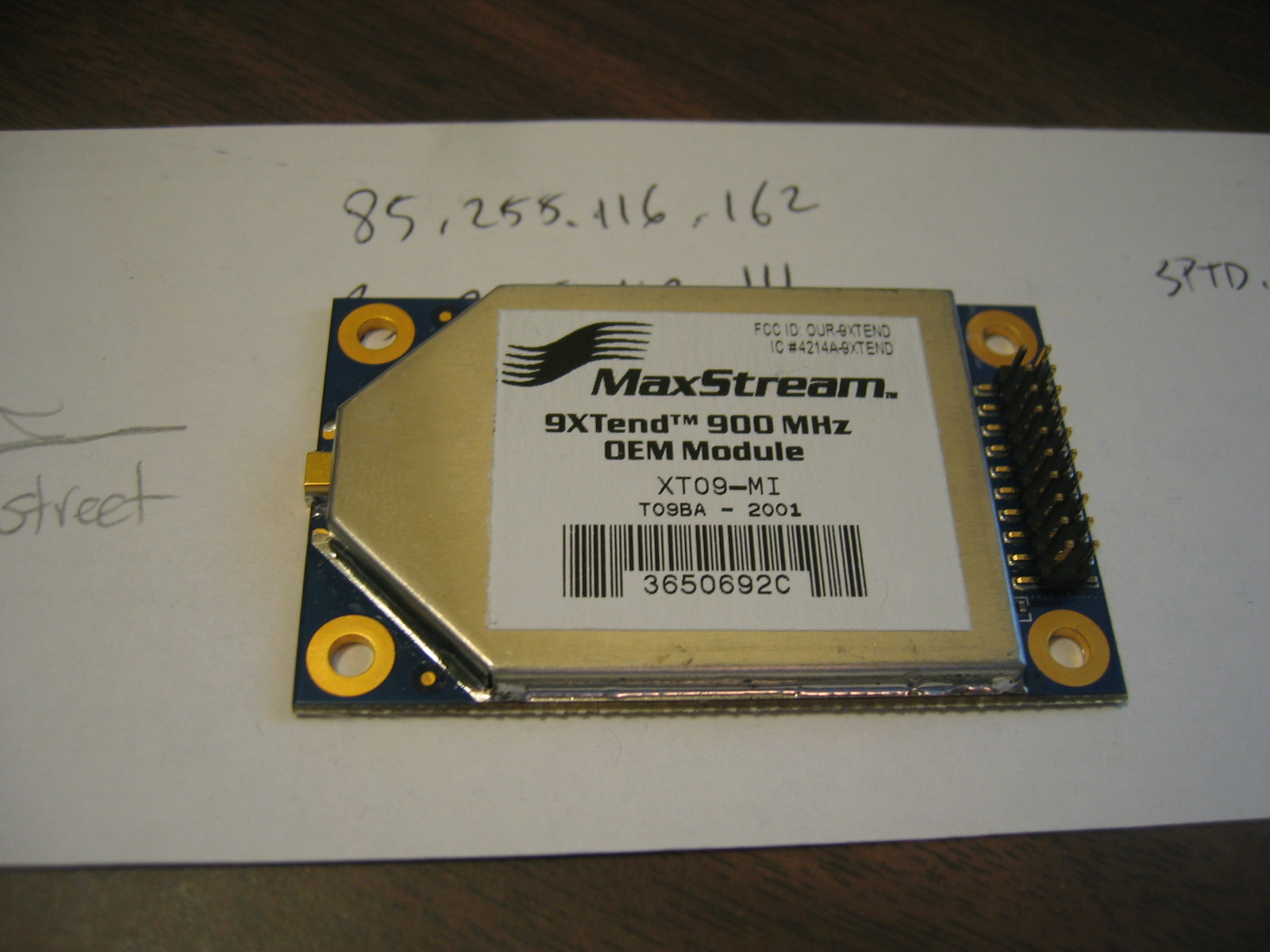
| In store for tomorrow is this... the Maxstream 9XTend RF module. I'll only need 4 pins to work with initially (Vcc, Gnd, DataIn, and DataOut). |
| Oct 16, 2006 |
|
| So it took about two days to sort out a few of the necessary settings needed to consider for the
RF mod. There's still quite a bit to consider, but so far, just the basics for simple TX/RX comm
should be enough. Nothing happened when first hooked up. It was quite frustrating; I connected
Vcc, Gnd, DataIn, and DataOut as specified, but nothing happened. I soon realized that my UART2 was not
initializing. So I unplugged the GPS from UART1, and put the RF mod in its place... still no dice. So after browsing the 9XTend product manual, I noticed I forgot one critical piece. There's a active low Shutdown signal that must be set high to use the RF module. DuHhh!! So that did it, but I still had no UART2. After a while I got a reply from a post to Netburner support stating that the UART2 setup has an issue such that its internal register bits may be overwritten if another UART is setup afterwards. This was my case. So it was a Netburner bug. The work around was a simple change of code, but now I'm passing data out the UART2. The radios are working partially. I can receive on my MCU-side from the Desktop terminal, but I can't transmit in the other direction... weird? I'll have to work out a few more ideas to see what's up with this later. |
| Oct 18, 2006 |
|
| Now the radio can send. The problem was a simple thing that I overlooked. The radio is defaulted for 1 Watt transmission. A spec table in the product manual states that 1 Watt transmission does not work at 3.3 V; it must be 4.5-5.5V. Well my source was 3.3V, so another easy fix, just had to change the TX Power to 500mW. Now data is moving out the radio on command. There's a lot of current pulled from this radio with the setup I have. The 600mA draw at 500mW should only occur during transmission. My tests were not constantly sending, so I have another thing to figure out, or else the device will drain a battery quite fast. Till next time... |
| Oct 26, 2006 |
| Not much work this passed week due to lots of other classwork. I implemented a simple message sending routine for forwarding a comma delimited message of position data out the radios. Unfortunately, after I added this code, my darn GPS would never get a fix. I let it run for hours on end and nothing. I was starting to think that my GPSs were burned out. Well fortunately they weren't. I repositioned the mod on my desk and lo' and behold, a position fix was obtained in about 5 minutes. I guess sitting close to my window sill wasn't doing it (even though you'd think that would be the optimum spot for an antenna)?! So using my added push button, a simple press beamed my position at 100mW to the receiving end at my desktop computer. The pic below is some received position messages (MSG_TYPE,lat,lon,alt,hdg,spd) on a terminal. |
|
|
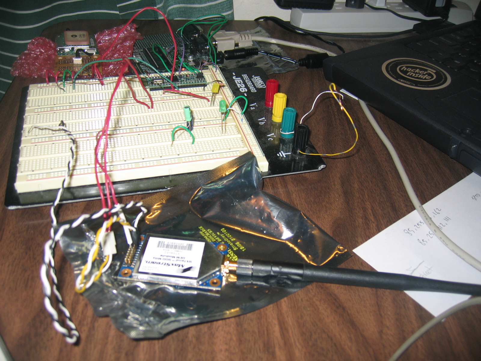
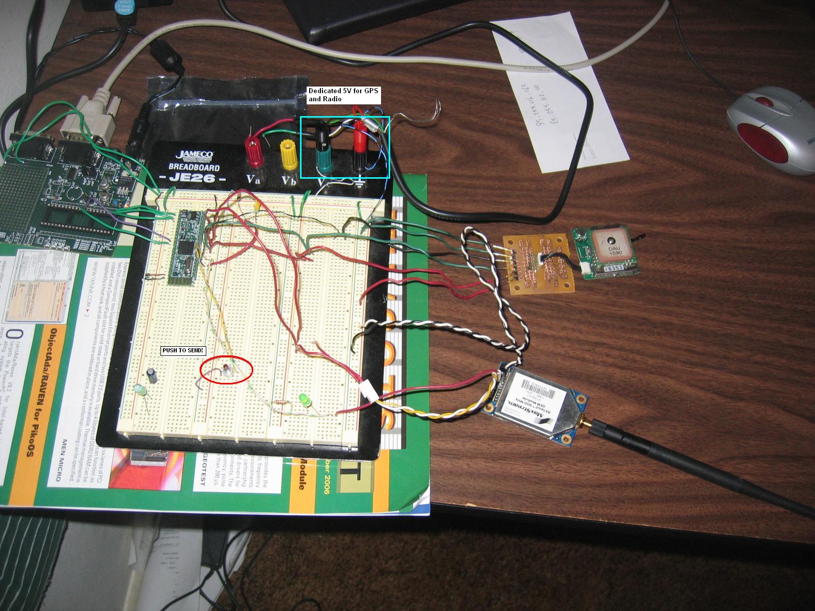
| Here's the new layout of components. A push button (highlighted in red) sends current message data out the radio. I also gave the GPS and radio a separate 5V supply to ease the draw from the dev board 3.3V supply. Pulling all that power from the little dev board sure was making the 3.3V LM2937 regulator super hot. |
|
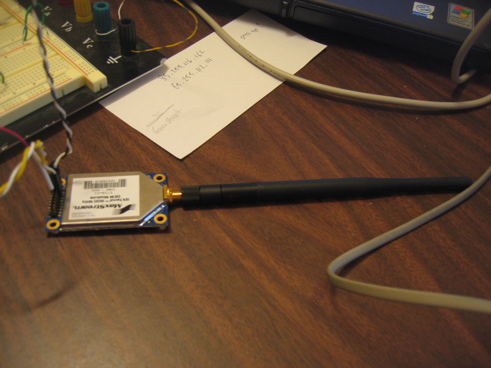
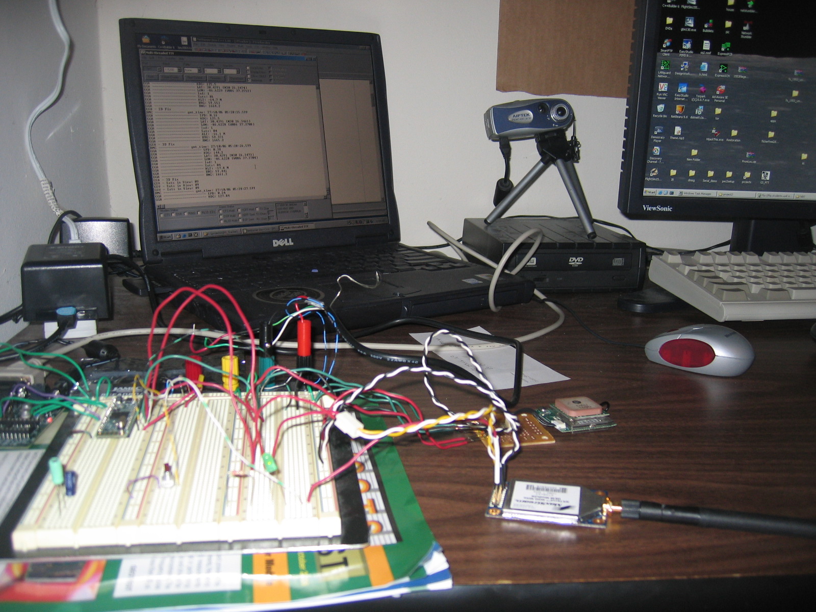
| Here's another view of the new setup. |
|
|
| Here you can see the sending and receiving antennas. |
|
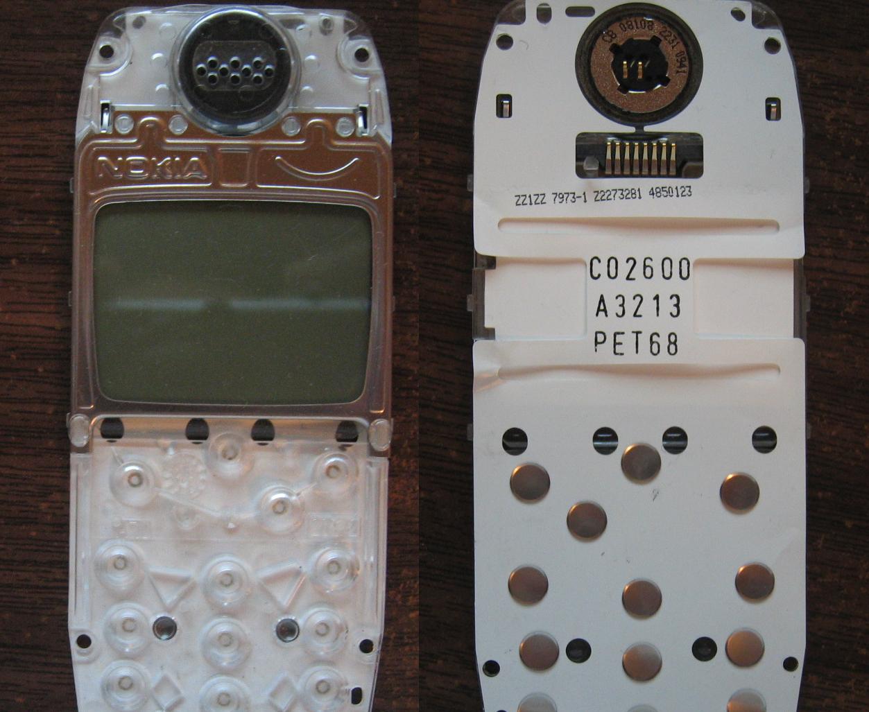
| The new Nokia 3310 LCD came in on the weekend. It has a better interface on the back for easier connecting. |
| Oct 29, 2006 |
| Tested the new LCD at the lab with Jon. We built a small connector using parts of an old PCB board. The connector was just metal pads, so we had to hold the LCD connectors to the pads... and when we ran the lcd software - no luck. Some of the connectors were a bit off. It's possible we aren't making a good enough connection. Oh well, I'm going to try to find some ribbon cable and just go ahead and solder it to the LCD connectors... till wednesday. |
| Nov 1, 2006 | |
| Well I got some nice ribbon cable from Tom at work and brought it to the meeting today. Jon went ahead
and soldered it nicely to the LCD connector pins. We plugged it in, and YAH! the LCD lit right up and showed
a few lines (we just had it send 3 bytes of hex 76). Awesome! However, it wasn't that awesome. We then tried to send a character (an ampersand) to the display. After recompiling and then running, the display did nothing. Did we just burn another one?! Fortunately we didn't. After a while, we found that it ended up that we had the contrast setting too low :). We also were sending 1 extra empty byte so the displayed data had a gap between each 8-bit pixel string. But that wasn't too hard to fix. Now it's just the tedious job of coding some nice routines to draw to the display. So all the main hurdles have been met. Jon took the board for the weekend to work the LCD code. Hopefully soon this little thing will start coming together really nice! -- more pictures next time. |
|
| <==Back | Next==> |